LATEST RELEASE: BetaMatch version 3.4.0 - Get it here!

In mobile phone applications it often happens that the power amplifiers (PA) are far from ideal and that the maximum output power is achieved at a load impedance that significantly deviates from 50Ω. This means that many times it is worth the effort to match the antenna to the PA’s optimum load impedance rather than to 50Ω at the TX-part of the bands. This is commonly referred to as Active Matching.
BetaMatch has built-in features to facilitate matching and optimization for sources that have:
In order to perform this kind of matching it is necessary to first find out at what impedance the PA delivers maximum power (and the value of this maximum power).
The place to change Zs and Ps in BetaMatch is in the source editor. The source editor can be opened by clicking on the source in the network plot. It can also be opened from either the View or the Component menus.
When first opened the source editor looks like this:
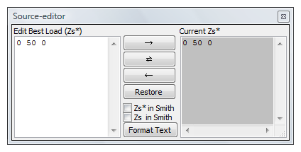
The source editor consists of 3 parts:
The controls in the center row are from the top:
Note
The optimum load (Zs*) is the value that is used to describe the source. Note that it is the conjugate of the optimum source impedance. This is by convention and is also convenient since normally the Zs* is the value that is measured by most load-pull measurements.
The source is changed by entering rows in the editor window. Each rows consist of at least 3 numbers:
The values given describes the source impedance and output power from that frequency until new values are given. The default row when the editor is opened:
0 50 0
means that Zs* = 50Ω and that Ps = 0 dB (100%) from 0 MHz and on-wards. This line describes a constant default source. To change this a new row must be added.
Example 1:
  0      50    0
880  25  -25
915      50    0
The above describes a source with Zs* = 25 - j*25 Ω in the frequency range 880 - 915 MHz and Zs = 50Ω for all other frequencies. Since the there is no data in the 4th column Ps is assumed to be constant 0dB (100%).
Remember that it is the conjugate of Ps that is given in example 1 above. Zs = 25 + j*25 Ω for frequencies in 880 - 915MHz.
Example 2:
0    50  0          0
880  50  0  -0.75
915      50      0          0
Example 2 describes a source with a constant Zs* = 50Ω everywhere. The output power, Ps, is 0.75dB lower in the TX-part of the GSM900 band (880 - 915 MHz). When an optimization is run it will compensate for this and give a weight of 0.75dB to this part of the band. In the optimization results the 880 - 915 band will have higher efficiency than other frequencies.
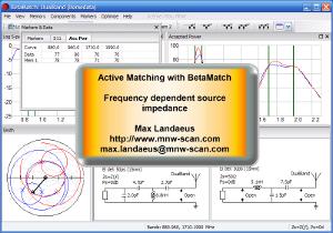
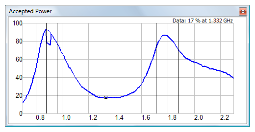
An optimized curve with Ps as in ‘example 2’ run for GSM900 and GSM1800 bands is shown below. The thick line describes the actual output (with the varying output). The thin line shows the efficiency (as if the output was 0dB for all frequencies). Also notice that the efficiency is higher for the low band than for the high band. This is because the optimizer is compensating for the decrease in output power on the TX-part of the GSM900 band.
Example 3:
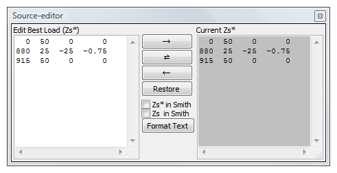
This example shows a combination of examples 1 and 2. Here both the impedance and the output power varies. Below is a figure to show what it looks like in the source editor when the data have been entered and transferred to the Zs* window with the ← button.
Tip
Although there is no load or save function in the source editor it is still possible to select, copy and paste text into and out from the editor window. If you have a more complex set of data you can save it in a normal text file and copy it into the source editor when you need it. Copy, cut and paste can be done via the context menu or with the normal shortcuts (ctrl-c, ctrl-x and ctrl-v respectively)
Tip
You can change the font-size in the source-editor by holding down the control-key while rotating the scroll-wheel.
Note
In BetaMatch the source is treated as a generator (transmitter), but it could just as well have been regarded as a receiver. The reason for choosing the ‘transmitter’ approach is purely practical since most of the time it is the amplifiers that deviate from 50Ω, whereas the receivers normally is close to this value.