LATEST RELEASE: BetaMatch version 3.4.0 - Get it here!

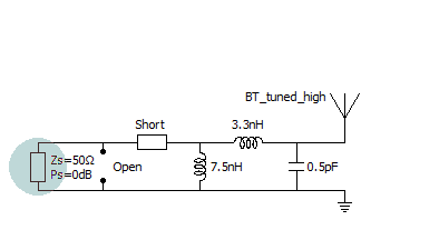
It is possible to replace any individual component with an LC-net. For series components a parallel LC-net will be inserted and for shunt components a series LC-net will be used (see figure below).
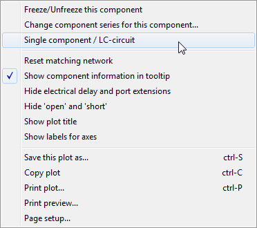
Components are toggled between single component and LC-net via right click on the selected component and choosing Single component/LC-circuit from the context menu:
Component values are changed in the same way as for single components, that is left click and change the value from the list of components that pops up. However, for an LC-circuit both an inductor and a capacitor needs to be selected for the component to have effect. Notice that in the series position both components are Short by default and in the shunt position both components are Open. This means that the LC-combination will not have any influence until both inductor and capacitor values have been selected.
Notice that optimization with nets containing LC-circuits will take longer time than with nets that only consists of single components. This is because an LC-circuit roughly corresponds to two components; thus a 3-component optimization where one component is an LC-circuit will take about the same time as a 4-component optimization.
When optimizing with LC-circuits, single components are also included. If the best net contains a single component instead of a LC-circuit the LC-net will be changed to a single component automatically. When this happens you will need to manually restore these components to LC-circuits if you wish to run more optimizations.
Since an LC-circuit is treated as a single component freezing an LC-circuit will freeze both the L and the C.
Any component can be frozen by selecting Freeze/Unfreeze this component from the context (‘right click’) menu in the network plot.
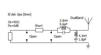
The optimized network will always be located as close to the antenna as possible. This needs to be considered when a component is frozen: The results of an optimization will depend on if component(s) that are frozen are inside the matching network or not. For example: if the series component closest to the antenna is frozen and optimization for PI-net is chosen, the actual optimization will only be for the two shunt components since the series component is fixed (see figure below where the series component is frozen to 3.9pF).
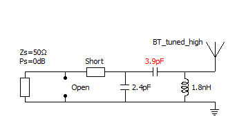
The PI-net after optimization when the series component is frozen.
On the other hand, if the series component that is closest to the generator is frozen the result from optimizing for PI-net will look as below. This case will result in a 4 component network where 3 components have been optimized.
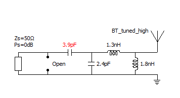
An optimized PI-net when the frozen component is outside.
To find the best PI-net with a frozen component on the antenna side chose 4 component optimization (type B - with series component closest to the antenna). An alternative is to freeze the two components closest to the antenna and optimize for 5 components. Both of these alternatives will give a 4 component network where 3 components have been optimized. The latter alternative is shown below.
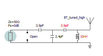
Freezing two components and optimizing for 5 components.
Finally, the best PI-net without any frozen components is shown below:
A PI-net with free optimization (no frozen components)