LATEST RELEASE: BetaMatch version 3.4.0 - Get it here!

This section describes briefly how to use the Network Plot Window to modify the current matching network. More detailed information can be found in the subsections
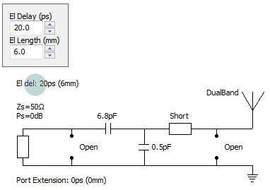
The graphical network consists of (from left to right):
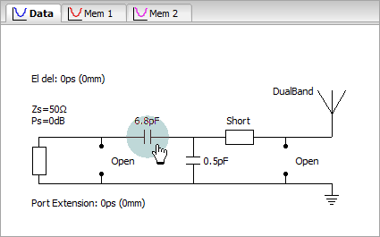
To modify any of these move the mouse until the desired item is selected, this is indicated by a light blue circle.
A component can be either an capacitor, an inductor or one of Open or Short.
Note
If you whish to change the whole component series (eg from 0402 to 0201 sized components) this is done in the Circuit Menu, see Select Component Series.
When a component is highlighted it can be changed by:
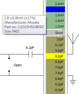
Inductors are greenish, Capacitors are brown and Open/Short are red. The current component is yellow and the component with the blue colour will be selected if the left mouse button is pressed.
The window can be moved with the mouse by pointing somewhere in the white frame and holding down left mouse button.
A small box with component information will popup when the mouse moves over the components (see below).
The list that is shown does not show all available components. Instead a shortened list is shown. The reasons for this are:
However, the components that are not in the shortlist are still available in sublists. A small arrow to the right of the component value in the short list indicates that there are more components close to this values that can be selected. When the mouse hovers over a component with arrow a sub-window with more components are displayed.
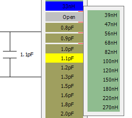
If a component from the sub-window is selected it will be temporary moved and will appear in the short list next time it is shown. It will remain in the shortlist until the component is changed, then it will be removed from the shortlist.
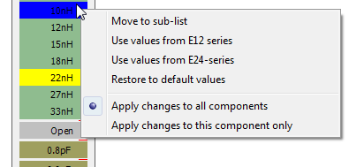
To more permanently change the component selection there are some options in the context menu that is displayed when right-clicking on the component list.
There is also, a slightly different, context menu when you right-click in the sub-list window:
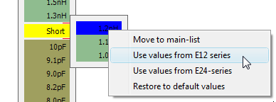
The options in these: menus are:
Note
The optimizer will only use components that are included in the main-list. This means that shortening the main-list (by using only E12 values for example) will make the optimization time shorter, but of course the best network may not be as good as if more components are included in the optimization.
Port Extension and Electrical Delay is used to adjust the reference plane. It is very important that the reference plane is correct - if the reference plane is incorrect all calculated matching networks will also be incorrect. The reference plane should be at the position where the matching network starts.
Port Extension versus Electrical Delay
Port Extension moves the reference plane of the measured data, whereas the Electrical Delay simply adds the delay to the port data. From this follows that for a Port Extension of 20ps an equivalent Electrical Delay would have to be set to twice the value, i.e. 40ps.
Older VNA models may only have Electrical Delay, whereas more modern instruments have Port Extension (and maybe Electrical Delay). Nowadays it is preferred to use Port Extension. For instruments with more than one port the Port Extension can be set individually for each port. Electrical Delay will add the same value to all ports.
Normally Port Extension is included in the saved Touchstone file when data is saved from the VNA. However, Electrical Delay may or may not be saved depending on model (and in some cases on the instrument setting when the data is saved).
Always check that the reference plane is correct by comparing the Smith Chart on the VNA with the Smith Chart in BetaMatch. If the plots are not the same the delay or port extension needs to be adjusted.
To change the Electrical delay click on the text just above the source. Port Extension can be changed by clicking on the ‘Port Extension’ text at the bottom. Use one of these controls to change the delay/extension of the active 1-port data if it is not already included in the loaded Touchstone-file:
Left click will open the source-editor where the impedance and power level of the source can be controlled. See Source Editor for information on how to change the source.
Left click will open the ‘Load TS-file’ dialog if you have a valid license. Otherwise the menu to load ‘Demo Data’ is shown.
Right click anywhere in the Network Plot window to bring up a context menu:
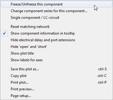
This context menu has the following options:
Freeze/Unfreeze this component: When the selected component is ‘frozen’ the component value can not be changed. This also means that the value will be constant during an optimization. It is possible to freeze any number of component and frozen components will have their component value printed in red color.
See the section “Which component to freeze? ” for some special details to consider when choosing which component to freeze.
It is only possible to freeze components. Trying to do this for non-components, such as the antenna or the source, will give an error message.
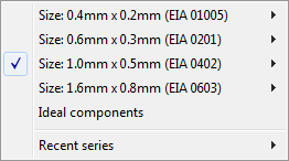
Change component series for this component: This makes it possible to use different component series at different positions in the matching network. The change will only affect the currently selected component.
The selection is done via a pop-up menu similar to the Components Menu (see figure below). More details on how to change component series is described in the section Select Component Series. Components with individually selected component series will have their component value printed in italic to distinguish them from components that use the global component series.
Notice that changing a component series will cause a reset of the whole matching network.
This option only works for components and trying to change the component series for non-components will cause an error message to be displayed.
Single component/LC-circuit: Either a single component or a LC-circuit can be used at any component position. See the section on LC-circuits .
Notice that this option is only available for components. Trying to use it on non-components will cause an error message to be displayed.
Reset the matching network: This will restore all components to either ‘Short’ or ‘Open’ and also reset the ‘Electrical delay’ to 0ps.o
Show component information in tooltip: When this option is turned ON (ticked) a tooltip window will display information about the currently selected component. The window will also be displayed in the circuit window for Memory 1 and 2 showing information for the component that is closest to the cursor. The information that is showed is: tolerance, manufacturer, part number and component size. Information will only be shown for actual components (no window will be shown for OPEN or SHORT).
The information window can be turned off by unticking the menu item.
Hide electrical delay: When copying the network into other documents (see below) it is often no need to include the Electrical delay. Toggle this option to Off will hide it, in order to do any changes to the current delay it must be On.
Hide ‘open’ and ‘short’: This will remove any unused components which may be useful before copying the matching network into other documents.
The other options in the context menu are common for all figure plots and described in Zoom & Drag.
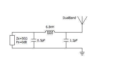
A PI-net where both Electrical delay and open & short are hidden.